Please note – Drainage of water away from pavements has been an important consideration  in road construction for more than 2000 years. This chapter addresses some basic surface and subsurface drainage considerations that should be evaluated in the design and construction of all pavements. Many localities have established certain standards and requirements for pavement drainage, as has the Virginia Department of Transportation. All applicable sections of these state and local requirements should be followed. The information contained herein is provided as an additional reference source for basic design and construction considerations.
I – General Pavement Drainage
Since the Romans began building long-lasting roads highway engineers have recognized the critical necessity of good drainage in the design and construction of any type of pavement. Probably no other feature plays as important a role in 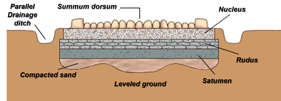 determining the ability of a pavement to withstand the effects of weather and traffic and in providing trouble-free service over long periods of time.
However, modern materials processing, handling, and placement often result in base and subbase courses that do not adequately drain or transmit water. Traffic volumes and loads with accentuate this problem and often lead to moisture induced premature and catastrophic pavement distress.
Pavement designers need to understand and analyze the conditions under which the pavement must function. Highway/pavement geometrics, surface drainage, non-pavement subsurface drainage, climate, and soil properties all have a significant impact on drainage design. With this information the designer is able to; (1) predict the amount of free water that will enter the pavement structure; (2) to predict surface free water/runoff; and (3) establish the design subgrade moisture content.
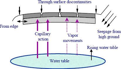
The primary source of water in pavements is precipitation (rain). This water can enter the pavement through several ways; cracks, infiltration from shoulders and ditches, high groundwater, etc. The water is also moved by an energy gradient, such as gravity, capillary forces, osmotic forces, and temperature or pressure differences.
Free water can be removed by draining vertically through the subgrade or laterally through a drainage layer. Several combinations of criteria and equations can be selected to calculate the required permeability of the drainage layer. The criterion selected has much more influence than the equation used; therefore, the drainage criterion should be selected carefully. Then the drainage layer and/or base can be designed to meet the selected criterion. The materials specifications should be checked to assure that permeability, strength, load-distribution, and construction stability requirements are met.
Water is also present in pavement materials in the form of free water, capillary water, bound moisture, or water vapor. Free water is the form of most concern to the designer because it can decrease the strength of the pavement and is the only form of water that can be significantly removed by gravity drainage.
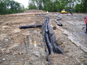 The accumulation of excess water in untreated aggregate courses or in the subgrade underlying any pavement structure may cause damage in various ways. In wholly or partly saturated soils, the application of dynamic loads causes pore pressures which reduces the internal friction and lowers the resistance to shear. A similar reduction in strength occurs when a roadbed is wholly or partly saturated. Some soils have a high volume change when water is added, causing differential heaving and weakening of the pavement structure. The accumulation of water from below by capillary rise or in the form of vapor can be prevented by lowering the water table or by constructing a vapor barrier.
Most subgrade soils consist of very fine materials (silt and clay) that weaken when wet. When a subgrade is not properly shaped and sloped for drainage, water may collect on its surface, beneath the pavement layers, and cause it to lose stability and support. Repair of pavements contaminated in this manner may require complete removal of the entire course and replacement with clean material.
Overall Drainage Plan
In developing the various features of a drainage system, consideration should be given to its principal purposes. They are:
- Collect and drain off surface and subsurface water
- Prevent or retard erosion of embankments
- Intercept water from surrounding areas and carry it away from the pavement
- If necessary, to lower the groundwater table
Proper drainage design is an essential feature of the overall pavement design and should be considered along with it. The factors to be considered in developing the drainage plan include the following:
- Size of area to be drained
- Expected maximum rainfall
- Slope of the surrounding terrain and probable rate of runoff
- Characteristics of the subgrade soil, including its permeability
- Presence of springs or other underground water
- General elevation of the groundwater table
- Minimum depth of cover required to protect pipe from traffic loads
This section presents some general information dealing with these factors. However, a detailed discussion is beyond its scope and purpose. Where the project is large enough to warrant the expenditure of the necessary funds, a qualified engineer should be entrusted with developing the drainage plan. In most cases, a comprehensive engineering study will be justified by the subsequent saving of large maintenance and repair costs. In other cases, the design may be approximated from local practices.
Draining Types
 | 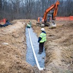 |
There are two basic categories of drainage problems – surface drainage and subsurface drainage. Surface drainage includes the disposal of all water present on the surface of the pavement and nearby ground. Proper surface maintenance procedures will help minimize the intrusion of surface water into the pavement through joints, cracks and other surface openings. Subsurface drainage deals with water in the several pavement courses and in the surrounding soil. Such water may enter through an adjacent porous material, or from the ground below.
These drainage categories are discussed separately and in more detail later in this chapter.
Erosion
One of the purposes of a drainage system is to prevent or retard erosion. When water flows over soil, it tends to pick up and carry along some of the soil particles. When such soil-laden water is slowed down, the transported particles will settle and produce deposits of silt and mud. Therefore, a good part of controlling erosion is controlling the velocity of flow. This may be accomplished by directing the water over gentle, rather than steep slopes and installing baffles or check drains along the watercourse to slow the current.
Hydrostatic Head, Capillary Action & Water Vapor
When water flows into the pavement from surrounding higher ground and is not carried off at a sufficiently rapid rate, it will produce a hydrostatic head. This lifting force exerted on the pavement can cause upheaval and failure of the pavement structure.
Water will rise into untreated aggregate pavement courses from the underlying round either in liquid form under capillary forces or as water vapor (dense graded asphalt base courses are not susceptible to this action). Water entering the pavement structure in either of these forms will usually rise until reaching an impervious layer where, unless drained away, it will accumulate.
The level of the water table varies from season to season and in most areas may rise several feet after a heavy rain. If the grade cannot be raised, drainage may be needed to prevent the water table from rising into the untreated pavement structure.
Flow of Water within the Pavement
A common drainage problem is water flow within the pavement structure. The pervious layers of the pavement structure may offer the easiest path for the water to flow. Unless drained away, such water will flow downhill within the entire pavement structure until it collects in a low area, causing pavement failure. Also, it may saturate and weaken the subgrade.
II – Pavement Surface Drainage Design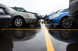
Protection of the pavement structure that is not full-depth asphalt from the action of surface water is most easily accomplished by a full-width asphalt surface. This means that the top layer of the pavement, including the shoulders, is constructed to provide impervious cover that will prevent surface water from entering the pavement structure from the sides. The pavement surface should be free from holes and cracks, have a permanently tight joint with the shoulder or gutter, and be shaped and sloped (crowned) for adequate runoff. Surface water usually is collected at the edges of the paved surface in ditches or gutters; these carry it to lower ground or to catch basins and storm sewers. On embankments, the water should be directed to asphalt spillways by means of asphalt curbs or dikes constructed on the extreme edge of the shoulder.
If a full-width asphalt surface is not used, the designer should consider making provision for removal of such water as may leak through it.
Pavement Crown and Slopes
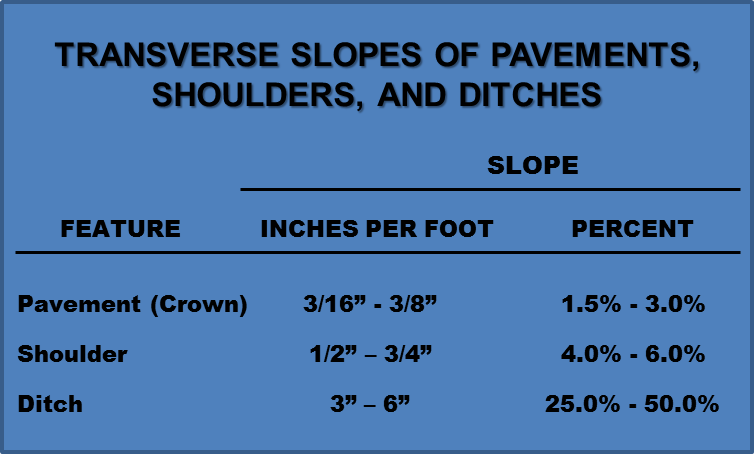 Highway and street pavements should be built with a crown or slope to facilitate the flow of water from their surfaces. The ·most common design practice allows the surface water to flow across the shoulder into a ditch or gutter at the side. Commonly used values for the transverse slopes of pavements, shoulders, and ditches are as shown in the chart below.
Shoulder Drainage
The best practice for shoulder drainage is to waterproof the entire shoulder with an asphalt surface. An alternative but inferior practice is to cover the shoulders with an aggregate graded to minimize seepage into the subgrade. Where a crown section is used for rapid drainage, the shoulder slope must be steeper than that of the pavement (See the chart above), but on a pavement uniformly sloped either to the outside or the inside (such as on a super-elevated curve), the shoulder slope generally is the same as that of the pavement. Sodded shoulders have some advantages in preventing erosion, but they tend to keep the shoulder material and the underlying subgrade in a moist and soft condition.
Curbs and Dikes
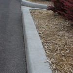 In some cases, a raised lip or curb, four inches or more in height, may be constructed at the outside shoulder edge to intercept the flow and guide it to some convenient outlet. This design sometimes is elaborated by shaping the edge of the pavement into a shallow channel.
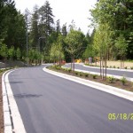
Medians
The wide median strip has become a standard feature of our modern multi-lane highways. Wherever possible, this median strip should be depressed; its valley being lower than the surface of the subgrade. Where conditions make a raised median unavoidable, an under-drain system should be installed.
Roadside Ditches
Drainage ditches are constructed along the edges of the roadway to receive the runoff from the pavement surfaces and water from subsurface drains. Where the slope of the surrounding area is toward the roadway, these ditches also 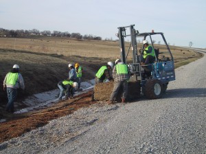 serve to intercept and carry away water that would otherwise reach the roadbed. V-shaped ditches should not be used as they promote erosion by concentrating water flow at their bottoms.
To increase the capacity of a drainage ditch it usually is preferable to widen rather than deepen. The side slopes of such ditches usually vary from about four-to-one for the slope nearer the roadway to about eight-to-one, or flatter, for the far side. The ditch should be big enough to accommodate all the surface runoff from the design storm and should be constructed to a continuous smooth grade without depressions or pockets that will collect water.
Drainage of Cuts
Where the surrounding area consists of higher ground, as in a cut, or where the pavement runs along the side of a hill, consideration should be given to the possibility of water flowing toward the roadway, either on the surface or at shallow depths through water bearing strata. A ditch constructed at the back of the top of the cut, or on benches in the cut slope, will intercept and carry the water away.
Drainage of Fills
Where there is a general slope of the adjacent ground towards a fill, it may be necessary to construct a similar type of interception ditch at the toe. If the embankment is not more than about ten feet high, the ditch may be placed adjacent to the toe and about 12″ deep. For higher fills or large amounts of runoff, it may be advisable to separate the ditch from the fill.
Parking Lot Drainage Design
After the plan of the parking area has been established, a parking pattern making 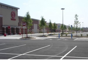 the most economical use of the available area should be worked out. When this pattern has been determined, drainage grades that obviate patrons stepping from cars into gutters can be designed.
To avoid puddle formation in rainy weather, a minimum 2 percent (1/4” per foot) grade is necessary for all places used by pedestrians. On sloping terrain, the establishment of this grade presents no problem, but on flat sites, the built-in drainage valleys will give rise to a gently undulating surface. To avert objectionable ponding on the paved area – or excessive flow – buried conduits may be required. Flows to proposed inlets should be calculated for existing conditions of runoff and, if necessary, spacing should be adjusted to give satisfactory results. For average conditions, inlet spacing of no more than 200 to 400 feet will be satisfactory.
III – Subsurface Drainage
Subsurface Water
The free water that percolates through or is contained in the soil beneath the surface is called subsurface water. When it emerges or escapes from the soil, it is termed seepage water and the point of emergence is called a spring or seepage area.
There are several forms in which subsurface water may be present: (1) water which is free to flow under the force of gravity, called “free water”, (2) water which moves under capillary forces, called “capillary water”, and (3) water in the form of water vapor.
The groundwater level may fluctuate with the seasons or because of withdrawal for irrigation or domestic use. Seepage from water-bearing strata may fluctuate with the seasons or remain relatively constant, depending on the source.
Why and where are Underdrains Installed?
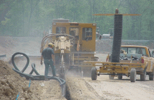 Subsurface drains are required at any location where water may enter or collect in the structural elements of the pavement. The location or identification of these areas requires a thorough study of the topography of the site, water table and considerable insight on the part of the engineer. The design should also be checked during construction as unexpected subsurface drainage issues frequently occur and should be addressed before placing pavement layers.
Subsurface drains may be required because of:
- A high water table in the area
- Active springs or seeps beneath the pavement
- Surface water entering the structural section
- Through a pervious pavement
- From a raised median
- From side ditches
If the source of water is through the pavement or from the median or side slopes, the first consideration should be given to preventing the entrance of water into the structural section. If this is not possible or cannot be assured, drainage facilities under the pavement must be provided.
U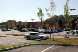 npaved raised medians invite difficult drainage problems. Regardless of the number of transverse drains employed, quantities of rainwater will drain from a raised median into the pavement structure and subgrade, weakening the pavement. The depressed median is recommended wherever possible, but when conditions make it mandatory to construct an elevated median, transverse drains should be connected with a longitudinal drain in the median deep enough to collect all groundwater before it can find its way into the pavement structure.
Subsurface seepage, under certain conditions, may develop a hydrostatic head sufficient to lift the pavement completely off the base, causing cracking and, in extreme cases, complete disintegration of the pavement structure. This problem is acuter when steep grades are involved. If not intercepted, subsurface water from a cut may flow out onto a fill and cause slumping of the fill slope and cracking of the pavement. The choice of filter material and the design of the drainage system must be given careful attention, considering both the type of material to be drained and the quantity of water to be expected.
DESIGN CONSIDERATION
In order to design a reliable subsurface drain of adequate capacity that can be constructed at a reasonable cost, it is necessary to:
- Determine, during the preliminary soil survey, the location of all seepage areas which may cause water to enter the structural elements of the pavement
- Determine the maximum rate of flow of water which may enter the structural section from any seepage and infiltration areas
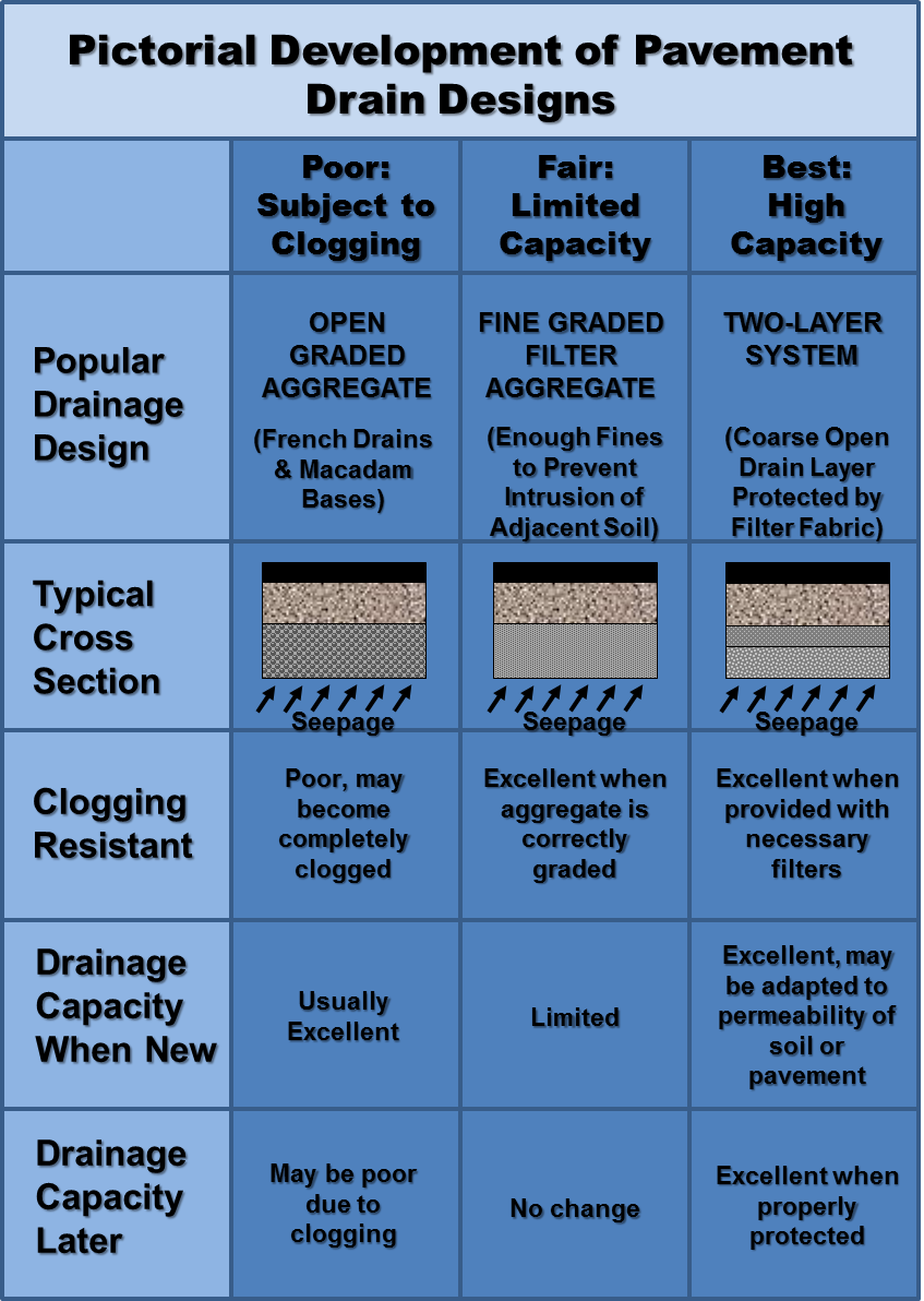
- Locate a source of aggregate suitable for filter material to prevent clogging of drains by water-borne soil
- Locate a source of aggregate which if needed may be used as drain rock to remove the water from beneath the pavement. (See Figure 3-1)
- Combine these materials into a design of adequate capacity to meet all requirements for the life of the pavement
CHECK THE DESIGN OF SUBSURFACE DRAINAGE DURING CONSTRUCTION
Regardless of the care used in the preliminary investigation, soil survey, and design of the pavement structure, it usually is not possible to determine exactly, from borings, the elevation of water-bearing strata or the rate of flow that will be developed. For this reason, it is essential that the engineer reevaluate the conditions and check the need for, and the adequacy of, any subsurface drainage indicated on the plans.
Any wet, soft, or spongy areas encountered at grade should be investigated and provisions made for their proper drainage. It should be remembered that even a minor rate of seepage can build up a large quantity of water over a period of time if a means of escape is not provided.
